What is Physically Based Rendering?
PBR (Physically Based Rendering) is a collection of rendering techniques that aims to mimic / roughly approximate how light and material interactions occur in the real world. This is crucial if we wish to make our renderers render objects that look ‘realistic and accurate’.
It provides a standard for the way materials are authored, something that is not possible with Non-PBR materials, since the materials designed for these models are often created for certain environments, and switching the environment may cause materials to look ‘wrong’ or ‘out of place’.
In a nutshell, switching to a PBR shading model leads to more realistic-looking materials (that look good independent of the scene/environment conditions), and provides a standard for artists to create materials. Before diving into what requirements are to be met to call a shading model as physically based, lets have a glance at the reflectance equation.
The Reflectance Equation
The reflectance equation is a more specialized form of the rendering equation.
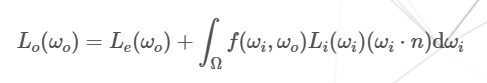
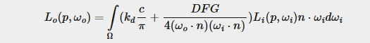
It is used to calculate the irradiance, which is the summation of radiance of all incoming light directions. Radiance is given by the amount of energy/strength of light coming from a single direction. The reflectance equation is given by :
 Source for image
In the equation,
- Lo(wo) is the summation of radiance / light that is directed along the view direction wo, for a particular point on surface.
- Le(wo) is the emissive radiance / light of the material directed along the view direction wo (independent of the light sources and light directions in the scene).
- The Integral is over a unit hemisphere centered around a point. The unit hemisphere aims to capture all possible values of wi, the incoming light direction.
- The term f(wi, wo) is the BRDF (Bi-Directional Reflectance Distribution Function) : indicates the contribution of each individual light direction wi towards the final radiance / light reflected along the view direction wo.
- Li(wi) is the incoming light radiance in direction wi.
- (wi.n) is the classic Geometry term visible in all shading models. ’n’ is the surface normal, and wi in the incoming light direction.
Go Here for a bit more detail on the rendering equation.
In simple terms, the rendering / reflectance equation calculates the light towards the viewing direction from a point on the surface, which is the sum of radiances of all incoming light directions over a hemisphere centered at said point, multiplied by the geometry term and the BRDF.
Note that the geometry term is included in the reflectance equation itself, and not in the BRDF. This is why the diffuse term of the BRDF does not involve dot product of normal and incoming light direction, and also why the specular term involves division by this term.
With the knowledge of the reflectance equation, we can finally get started with the theory behind Physically Based Rendering 🚀.
Requirements for a PBR shading model
PBR is not a set of strict rules that a lighting model must follow to be considered as physically based. It is more of a series of guidlines, which by following can increase realism of our scenes since we approximate/mimic the way physics works in the real world. The conditions a model must meet to be considered as PBR is :
(i) Microfacet model.
(ii) Energy conservation.
(iiI) Physically based BRDF.
Microfacet Model
Since we do not care about extremely minute irregularities on the surface, we assume that any irregularities that is smaller / close to the wavelenght of light (i.e the distance between two wave peaks) does not exist. At the microscopic scale, all surfaces could be described as a series of perfectly reflective mirrors, with varying surface normal orientations. If the light and view direction are oriented such that the half way vector is perfectly aligned with the microfacet normal, the light rays are more likely to scatter in a similar direction (i.e the specular reflections would be fairly concentrated and strong). This is a property of smooth surfaces. The rougher a surface gets, the more caotically aligned the microfacet - local normal will be, and the light rays would be scattered along seemingly random directions, giving wide specular reflections which are weak (i.e with low intensity).
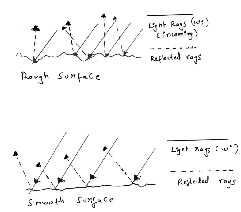
In the image, you can see that more rough the surface, more random the microfacet normal orientation is, and the more random the reflected rays are. This is what leads to the large specular reflections (which are weak and heavily blurred). On the other hand, the reflected rays from the smooth surface are roughly aligned towards the same direction, since the microfacet normals tend to be oriented roughly at same direction. This gives rise to sharp yet small reflections.
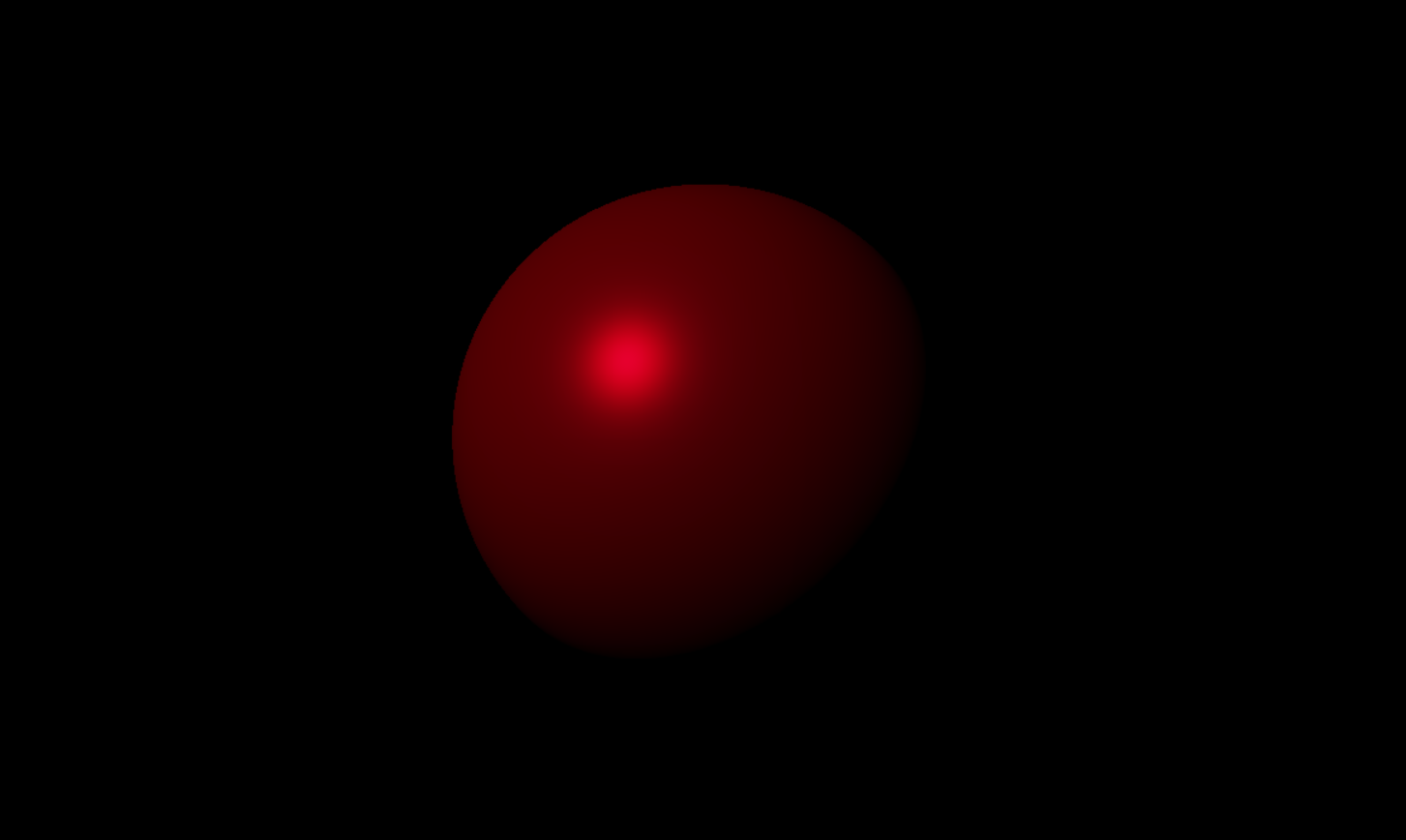
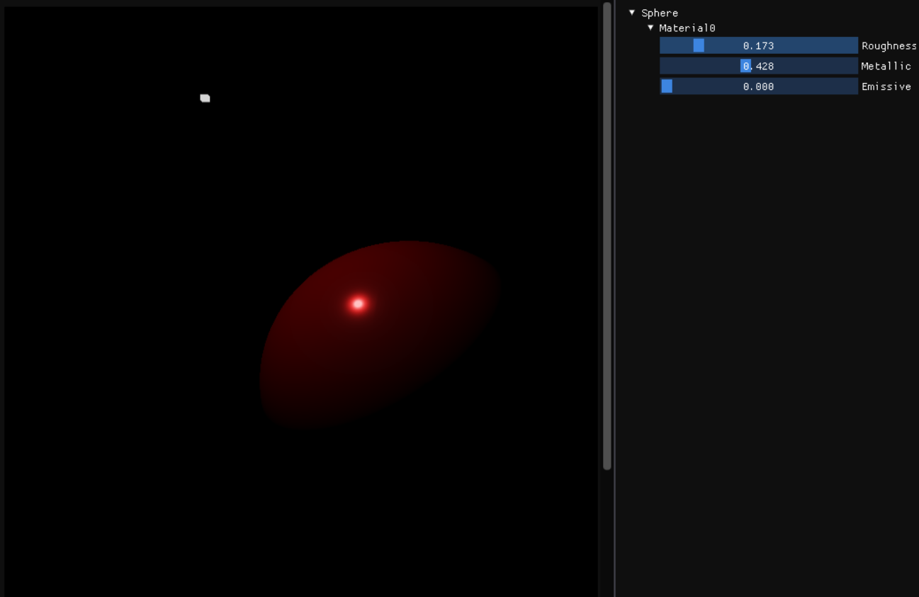 This is a smooth surface with a roughness factor of 0.173 and metallic factor of 0.428. Notice the strong specular highlight which is fairly sharp and concentrated in a particular region.
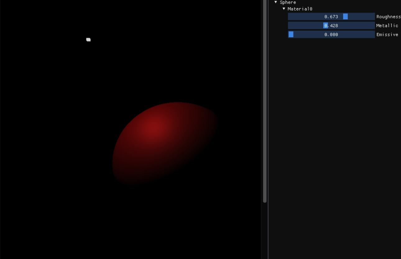 This is a rough surface with a roughness factor of 0.673 and metallic factor of 0.428. Notice that the specular reflection is spread out over a wide area, because the microfacets are chaotically aligned. The reflection is not concentrated in a region and weaker than the ones in smooth surface.
Energy Conservation
Enery is never magically ’lost’ or ‘gained’. The incoming light energy in PBR must equal to the outgoing enery (light energy due to reflection) plus energy lost due to internal scattering due to refraction, which is often converted in the form of heat.
When a rough surface exhibits specular reflections, we see that more and more rough a surface gets, the surfact has a large reflection shape combined with low intensity, when compared to smooth surfaces where the intensity of specular reflection is very high, but the reflection shape is small. This can be seen in the images in the above section as well.
Light does not just reflect. A portion of light will also be refracted into the surface and either absorbed by the surface entirely, where the enery gets lost in the form of heat, or the light rays might scatter interally and refract out of the surface with lower energy (as some energy is lost when the light ray collieds with particles).
The phenomemon where a light ray is interally scattered, is called subsurface scattering and will not be covered in this blog posts. We are only concerned with the light rays which get absorbed into the surfae and refract out of the surface within a very close range to the initial point of contact to the surface.
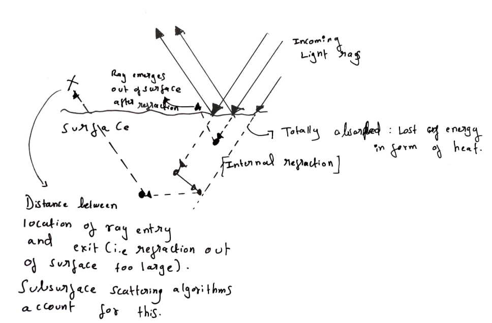
In the image, one of the light rays gets refracted into the surface, scatters internally, and refracts out at a close proximity to the point of entry. On the otherhand, the outgoing refracted ray that is marked with X leaves the surface too far from point of entry, and we ignore this.
The metallic property of a surface dictates what proportion of incoming light rays are reflected, and what proportion are absorbed. Metals typically have no diffuse color, since they completely absorb refracted light with little to no scattering. This changes as materials become more non metallic. Light that gets absorbed and scattered within close proximity to the point of entering the surface contributes to the diffuse color. [The light that gets reflected immediately contributes to the specular lighting, and the light that gets refracted and absorbed, scattered, and refracted out of the surface contributes to the diffuse lighting.]
Now, coming to energy conservation, if some light ray gets reflected, it will not be absorbed. The remaining light rays which are not reflected will get absorbed. That is, reflection and absorbtion are mutally exclusion, If a% of the rays get reflection, (100 - a%) of rays get refracted. This ensures that energy is conserved at all times, and is often ignored in non PBR shading models such as Blinn Phong or Gooch.
Physically Based BRDF
What is a BRDF? It stands for the Bi-Directional Reflectance Function. It is a four-dimensional function that takes as input parameters the incoming light direction, outgoing view direction, surface normal, and surface roughness parameter.
It computes the contribution of an individual incoming light ray wi to the outgoing radiance for a point along the view direction wo, given the surface material properties. The BRDF will use the energy conservation theory and microfacet model to approximate the reflective and refractive properties of a material (i.e the diffuse and specular part).
For a BRDF to be ‘physically based’, it must obey the Energy Conservation Principle stated above (the sum of light reflected for a point on the surface should never exceed the sum of incoming light at the same point on the surface). Since most real-time PBR renderers use the Cook-Torrence BRDF, let us look at that:
f(cook_torrence) = kD * f(Diffuse) + kS + f(Specular)
// Here, kD : Proportion of light rays that get refracted, scattered and refract out of the surface.
//       kS : Proportion of light that is reflected, and is also 1.0 - kD.
//       fDiffuse : Diffuse term of Cook torrence BRDF
//       fSpecular : The specular term of Cook torrence BRDF
Diffuse Term
The cook torrence BRDF uses the lambertian diffuse model with is just :
f(Lambert) = albedoColor / PI
Since the BRDF is scaled by PI, we divide albedoColor by PI to cancel out the effect. Also, the geometry term in other shading models (i.e normal . incoming light direction) is moved out of BRDF to the reflectance equation.
Specular Term
The specular term of the Cook Torrence BRDF is a bit more involved. It is given by the following equation :
f(Specular) = ((NDF) * F * G) / (4 (wi.n) (wo.n))
Where, NDF : Normal Distribution Function.
       F   : Fresnel equation.
       G   : Geometry shadowing / Masking function.
       wi  : Incoming light direction.
       wo  : View direction.
       n   : Surface normal.
Normal Distribution Function
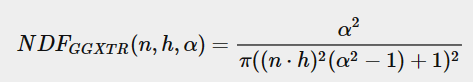
[D] Statistically approximates the number of microfacets whose normal is oriented exactly to the half way vector, based on the surface roughness, microfacet local normal, and the halfway vector. More rough the surface, larger the number of micofacets with normal perfectly aligned with the halfway vector will be and vice-versa.
Here is the GGX TrowBridge Reitx Model for NDF.
 Source : Learn OpenGL
// Approximates the number of microfacts on the surface whose local normals are aligned with the half way vector. For light to reflect from the surface (diffuse or specular)
// and reach our camera, the normal and halfway vector have to be aligned. More rough a surface is, more chaotically aligned the surface normals will be, producing large and dim highlights, while very smooth surfaces
// will produce very sharp and bright highlights since majority of microfacet normals are aligned to half way vector.
// This is the GGX TrowBridge Reitx model.
float NormalDistribution(float3 normal, float3 halfWayVector, float roughnessFactor)
{
    float alpha = roughnessFactor * roughnessFactor;
    float alphaSquare = alpha * alpha;

    float nDotH = saturate(dot(normal, halfWayVector));

    return alphaSquare / (max(PI * pow((nDotH * nDotH * (alphaSquare - 1.0f) + 1.0f), 2.0f), MIN_FLOAT_VALUE));
}
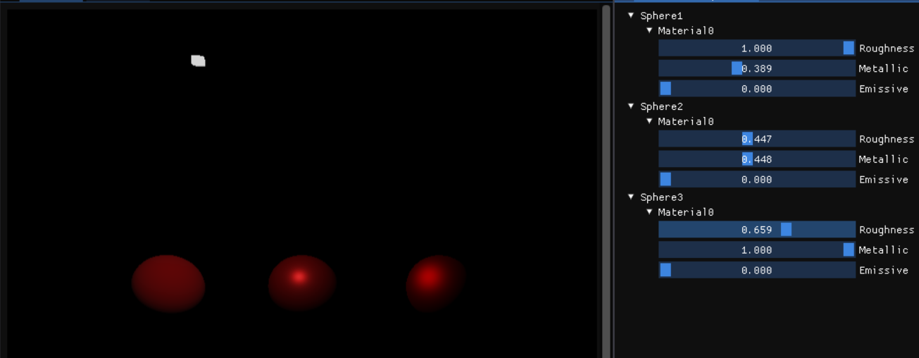
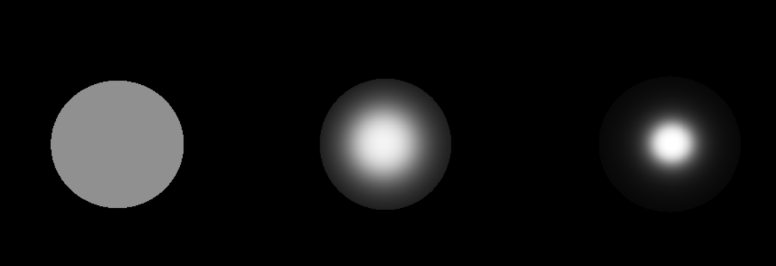 The left sphere has roughness value of 1, middle sphere has roughness value of 0.6, and the right sphere has roughness value of 0.3.
Lower the roughness, more concentrated the microfacet normal orientation is and similarly more rough the surface is, more widely distributed and random the normal orientations are.
Fresnel Equation
It approximates the proportion of light rays that get reflected rather than refracted for a particular surface based on the viewing angle.
When we look at a surface head-on, what we observe is the base reflectivity. When looking at parts of the surface at a grazing angle, the reflection becomes a lot more prevalent. Light is fully reflected from any surface at such grazing angles.
This approximation, however, is more for non-metallic surface than metallic-surfaces. Metals also have a tinted surface reflectivity which often gives metals their distinct color.
To handle both metals and non metals, we consider a purely non metallic surface to have base reflectivity of (0.04, 0.04, 0.04) and lerp between this value of base reflectivity (f0) based on the metallic factor of the surface.
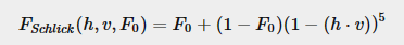
Here is the Fresnel shclick Equation:
 Source : Learn OpenGL
// Compute the ratio of reflected light vs how much it refracts.
// As the viewing angle increases, this ratio increases as well (quickly approaching one when angle becomes more and
// more oblique). f0 is the base reflectivity : the surface reflection at zero incidence. For non metals, it will just
// be a singular value in a float3 (v, v, v), but this is tinted for metals. Most dielectrics have a value of 0.04 as
// f0, but depending on how metallic a surface is it will be between 0.04 (metalness = 0) and the surface color
// (metalness = 1). cosTheta here is the angle between the halfway vector and the view direction. If the angle is 0.0,
// then said ratio is 1, and the light will be brightest here. Also acts as the kS term (where kS + kD = 1, due to
// energy conservation).

float3 fresnelSchlickFunction(const float vDotH, const float3 f0)
{
    return f0 + (1.0f - f0) * pow(clamp(1.0f - vDotH, 0.0f, 1.0f), 5.0f);
}
// f0 is computed by :
float3 baseReflectivity(const float3 albedo, const float metallicFactor)
{
    return lerp(float3(0.04, 0.04, 0.04), albedo, metallicFactor);
}
Geometry Shadowing / Masking function.
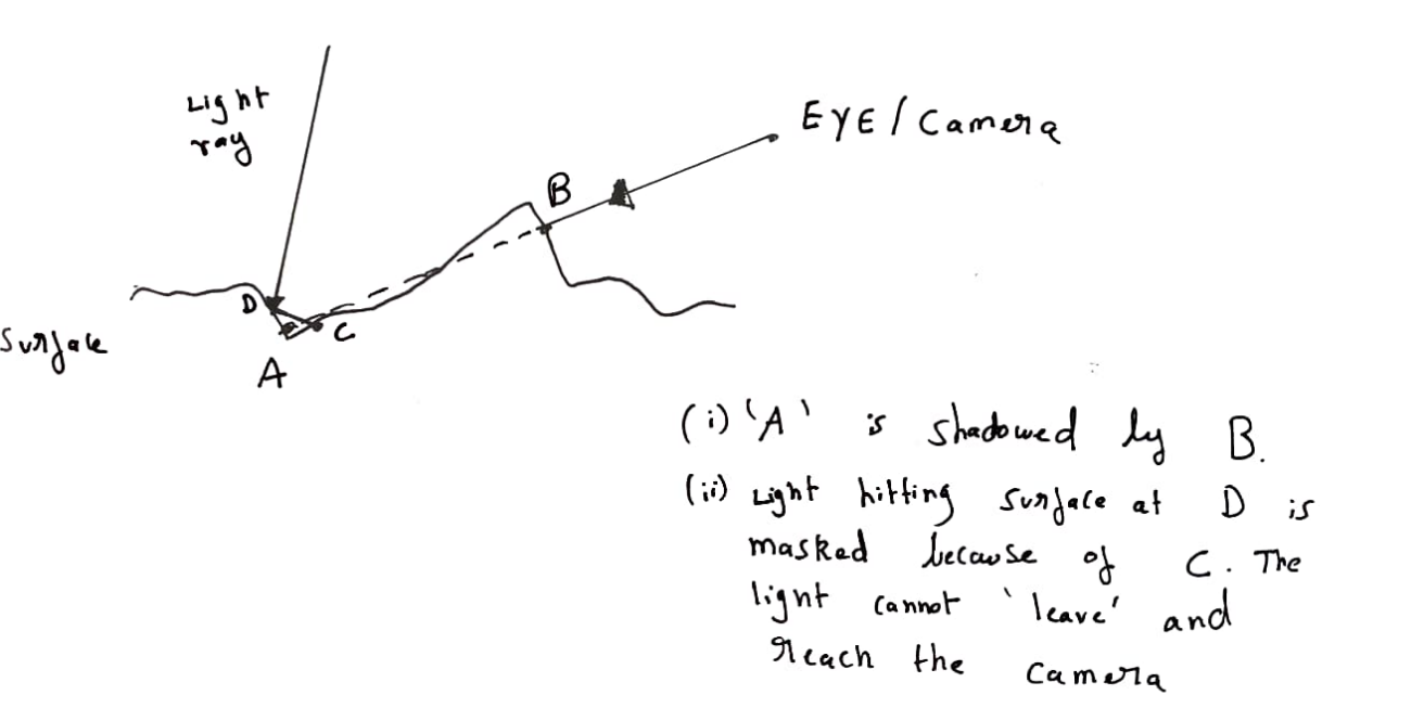 This function determines the number of microfacets that get shadowed or masked by other microfacets. More the roughness of a surface, the more probable these effects can be.
In our implementation, we actually use the same function to compute both the shadowing and self masking values. This is done by Smiths method.
The SchickBeckMann function is passed in the surface normal, roughness factor, and X. If X is the light direction, it computes self shadowing, and if X is view direction, it computes masking.
The final geometry shadowing/masking result is given by the smith function, which is the product of the schlick beckamnn geometry shadowing function with parameter X as view direction, and X as light direction.
This function determines the number of microfacets that get shadowed or masked by other microfacets. More the roughness of a surface, the more probable these effects can be.
In our implementation, we actually use the same function to compute both the shadowing and self masking values. This is done by Smiths method.
The SchickBeckMann function is passed in the surface normal, roughness factor, and X. If X is the light direction, it computes self shadowing, and if X is view direction, it computes masking.
The final geometry shadowing/masking result is given by the smith function, which is the product of the schlick beckamnn geometry shadowing function with parameter X as view direction, and X as light direction.
// Geometry function : approximates the number / relative surface area of the surface which is actually visible to us.
// If the surface is rough, several microfacets could overshadow and block others, because of which the light reaching us will be occluded.
// Using Smith's method, by changing the angle, we can approximate both self shadowing and geometry obstruction.
// Source :https://cdn2.unrealengine.com/Resources/files/2013SiggraphPresentationsNotes-26915738.pdf
// if x is viewDirection, then we are calculating geometric obstruction, and if light direction, we are calculating self shadowing.
float SchlickBeckmannGS(float3 normal, float3 x, float roughnessFactor)
{
    float k = roughnessFactor / 2.0f;
    float nDotX = saturate(dot(normal, x));

    return nDotX / (max((nDotX * (1.0f - k) + k), MIN_FLOAT_VALUE));
}

// Smiths method is used for approximation of geometry (both self shadowing and geometry obstruction). (ShlickGGX model).
// Uses SchlickBeckman formula to calculate both geometry obstruction, where the camera cannot see a point as some other microfacet is blocking it, or
// Self shadowing, where the light ray from a point is not able to reach the camera.
float GeometryShadowingFunction(float3 normal, float3 viewDirection, float3 lightDirection, float roughnessFactor)
{
    return SchlickBeckmannGS(normal, viewDirection, roughnessFactor) * SchlickBeckmannGS(normal, lightDirection, roughnessFactor);
}
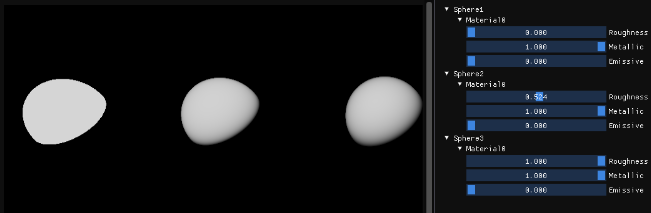
The result of the GeometryShadowingFunction is a multiplier. The first sphere has a roughness of 0.0f, and is pure white - implying no shadowing or masking is observed. The right sphere appears to be slightly dim, as it has a roughness value of 1.0, and is severely affected by self-shadowing and self-masking.
Cook Torrence BRDF
Finally, to compute the irradiance for a point (using cook torrence BRDF) the code is as follows (here, a deferred shading is used, with all vectors in view space):
float3 fresnelSchlickFunction(const float vDotH, const float3 f0)
{
    return f0 + (1.0f - f0) * pow(clamp(1.0f - vDotH, 0.0f, 1.0f), 5.0f);
}

float normalDistributionFunction(const float3 normal, const float3 halfWayVector, const float roughnessFactor)
{
    float alpha = roughnessFactor * roughnessFactor;
    float alphaSquare = alpha * alpha;

    float nDotH = saturate(dot(normal, halfWayVector));

    return alphaSquare / (max(PI * pow((nDotH * nDotH * (alphaSquare - 1.0f) + 1.0f), 2.0f), MIN_FLOAT_VALUE));
}

float schlickBeckmannGS(const float3 normal, const float3 x, const float roughnessFactor)
{
    float k = roughnessFactor / 2.0f;
    float nDotX = saturate(dot(normal, x));

    return nDotX / (max((nDotX * (1.0f - k) + k), MIN_FLOAT_VALUE));
}

float smithGeometryFunction(const float3 normal, const float3 viewDirection, const float3 lightDirection, const float roughnessFactor)
{
    return schlickBeckmannGS(normal, viewDirection, roughnessFactor) *
           schlickBeckmannGS(normal, lightDirection, roughnessFactor);
}

// BRDF = kD * diffuseBRDF + kS * specularBRDF. (Note : kS + kD = 1).
float3 cookTorrenceBRDF(const float3 normal, const float3 viewDirection, const float3 pixelToLightDirection, const float3 albedo, const float roughnessFactor,
            const float metallicFactor)
{
    const float3 halfWayVector = normalize(viewDirection + pixelToLightDirection);

    const float3 f0 = lerp(float3(0.04f, 0.04f, 0.04f), albedo.xyz, metallicFactor);

    // Using cook torrance BRDF for specular lighting.
    const float3 fresnel = fresnelSchlickFunction(max(dot(viewDirection, halfWayVector), 0.0f), f0);

    const float normalDistribution = normalDistributionFunction(normal, halfWayVector, roughnessFactor);
    const float geometryFunction = smithGeometryFunction(normal, viewDirection, pixelToLightDirection, roughnessFactor);

    float3 specularBRDF = (normalDistribution * geometryFunction * fresnel) /
        max(4.0f * saturate(dot(viewDirection, normal)) * saturate(dot(pixelToLightDirection, normal)),MIN_FLOAT_VALUE);

    float3 kS = fresnel;

    // Metals have kD as 0.0f, so more metallic a surface is, closes kS ~ 1 and kD ~ 0.
    // Using lambertian model for diffuse light now.
    float3 kD = lerp(float3(1.0f, 1.0f, 1.0f) - fresnel, float3(0.0f, 0.0f, 0.0f), metallicFactor);

    const float3 diffuseBRDF = albedo / PI;

    return (kD * diffuseBRDF + specularBRDF);
}


// -------------------------------------------------------------------------------------------------
// Lighting pass shaders (Vertex and Pixel):

#include "Utils.hlsli"

#include "Shading/BRDF.hlsli"

struct VSOutput
{
    float4 position : SV_Position;
    float2 textureCoord : TEXTURE_COORD;
};

ConstantBuffer<interlop::PBRRenderResources> renderResources : register(b0);


[RootSignature(BindlessRootSignature)]
VSOutput VsMain(uint vertexID : SV_VertexID)
{
    static const float3 VERTEX_POSITIONS[3] = {float3(-1.0f, 1.0f, 0.0f), float3(3.0f, 1.0f, 0.0f),
                                               float3(-1.0f, -3.0f, 0.0f)};

    VSOutput output;
    output.position = float4(VERTEX_POSITIONS[vertexID], 1.0f);
    output.textureCoord = output.position.xy * float2(0.5f, -0.5f) + float2(0.5f, 0.5f);
    return output;
}

[RootSignature(BindlessRootSignature)]
float4 PsMain(VSOutput psInput) : SV_Target
{
    ConstantBuffer<interlop::LightBuffer> lightBuffer = ResourceDescriptorHeap[renderResources.lightBufferIndex];
    ConstantBuffer<interlop::SceneBuffer> sceneBuffer = ResourceDescriptorHeap[renderResources.sceneBufferIndex];

    // Sample and extract data for the GBuffer's.
    Texture2D<float4> albedoTexture = ResourceDescriptorHeap[renderResources.albedoGBufferIndex];
    Texture2D<float4> positionEmissiveTexture = ResourceDescriptorHeap[renderResources.positionEmissiveGBufferIndex];
    Texture2D<float4> normalEmissiveTexture = ResourceDescriptorHeap[renderResources.normalEmissiveGBufferIndex];
    Texture2D<float4> aoMetalRoughnessEmissiveTexture =
        ResourceDescriptorHeap[renderResources.aoMetalRoughnessEmissiveGBufferIndex];

    const float4 albedo = albedoTexture.Sample(pointClampSampler, psInput.textureCoord);

    const float4 positionEmissive = positionEmissiveTexture.Sample(pointClampSampler, psInput.textureCoord);
    const float4 normalEmissive = normalEmissiveTexture.Sample(pointClampSampler, psInput.textureCoord);
    const float4 aoMetalRoughnessEmissive = aoMetalRoughnessEmissiveTexture.Sample(pointClampSampler, psInput.textureCoord);

    const float3 viewSpacePosition = positionEmissive.xyz;
    const float3 normal = normalize(normalEmissive.xyz);

    const float ao = aoMetalRoughnessEmissive.r;
    const float metallicFactor = aoMetalRoughnessEmissive.g;
    const float roughnessFactor = aoMetalRoughnessEmissive.b;

    const float3 emissive = float3(positionEmissive.w, normalEmissive.w, aoMetalRoughnessEmissive.a);

    const float3 viewDirection = normalize(-viewSpacePosition);

    // Reflectance equation for reference.
    // lo(x, v) = le(x, v) + integral(over hemisphere centered at x)(fr(x, l, v, roughness) * li(x, l) * (l.n)dl
    // x is the pixel position
    // v is the view direction
    // l is the light vector
    // lo is the irradiance, while li is the light radiance
    // fr is the brdf term.

    float3 lo = float3(0.0f, 0.0f, 0.0f);

    for (uint i = 0; i < interlop::TOTAL_POINT_LIGHTS; ++i)
    {
        const float3 pixelToLightDirection = normalize(lightBuffer.viewSpaceLightPosition[i].xyz - viewSpacePosition);

        const float3 brdf =
            cookTorrenceBRDF(normal, viewDirection, pixelToLightDirection, albedo.xyz, roughnessFactor, metallicFactor);

        const float distance = length(lightBuffer.viewSpaceLightPosition[i].xyz - viewSpacePosition);
        const float attenuation = 1.0f / (distance * distance);

        const float3 radiance = lightBuffer.lightColor[i].xyz * lightBuffer.radiusIntensity[i].y;

        lo += brdf * radiance * saturate(dot(pixelToLightDirection, normal)); // *attenuation;
    }

    lo += emissive;

    return float4(lo, 1.0f);
}
Make sure to take care of division by zero errors wherever required 😄
A few sample images using PBR shaders are given below:
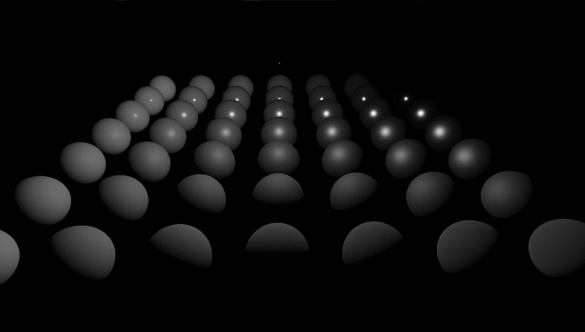 Bottom to Top -> Material becomes smoother.
Left to Right -> Material becomes more and more metallic.
Bottom to Top -> Material becomes smoother.
Left to Right -> Material becomes more and more metallic.
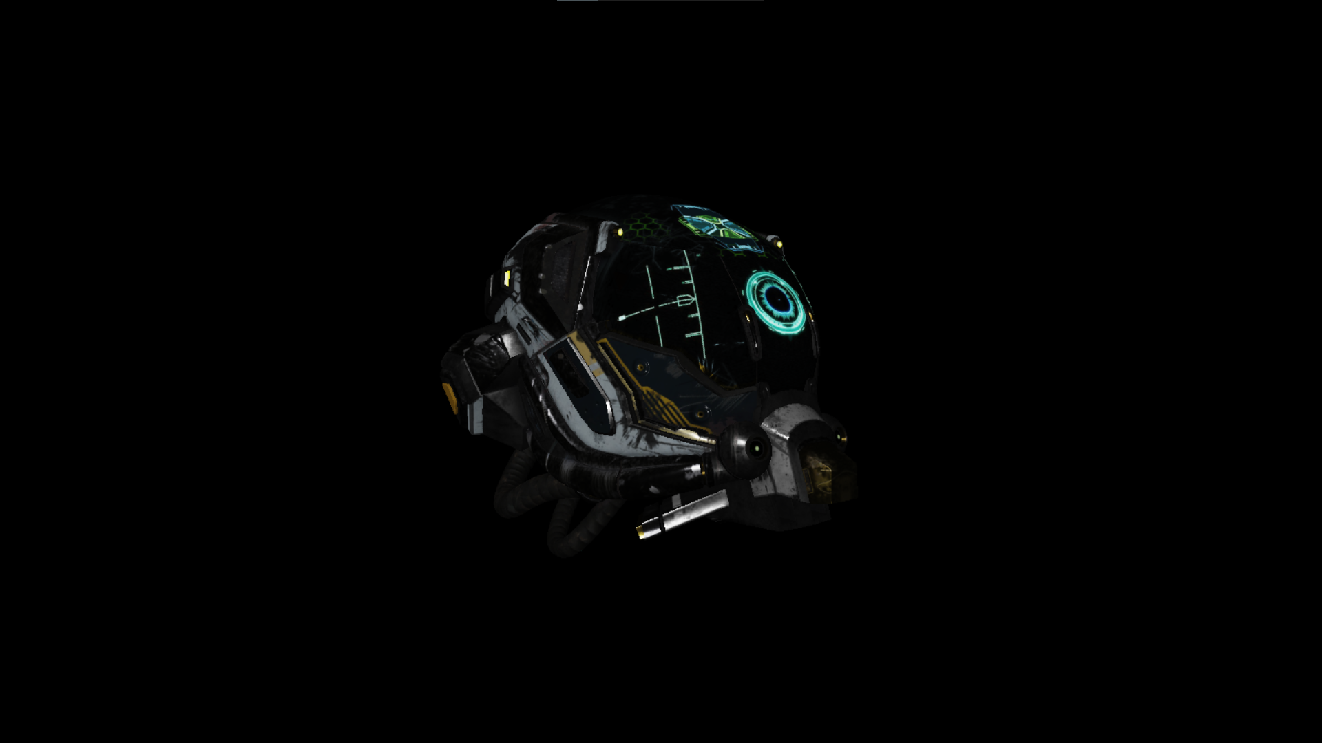
PBR Materials
Rather than having a constant buffer dictate the material properties for the entire object, consider using textures for albedo, ambient occlusion, metallic and roughness factors and normal maps. Using per-pixel material properties can boost the appeal of your render.
Note on Metals
To make metallic materials really pop out, consider looking int Image Based Lighting. Metals usually reflect most of the light that hits on them, and in the light rays they absorb, they do so completetly with no scattering, giving them the dull appearance since metals have no diffuse color. IBL takes into account the surround environment (by sampling into a cube map) and can give really visually appealing results.
Closing Thoughts
PBR offers a standardized solution to artist (and graphics programmers) to obtain realistic materials and renders. Note that PBR isnt a strict set of rules, but more of a guidline which may be broken in a few situations.
Most model loaders (especially GLTF loaders) will have support for PBR material loading, which you might want to look into (examples : FastGLTF, TinyGLTF, CGLTF).
If you wish to learn more about PBR (since it is a pretty big topic), check the resources linked below.
Thank you so much for your time! Feel free to leave comments if you felt something was lacking/incorrect or your opinions on my post! If you would like to reach out to me, head over to the Home page to find some contact links there.
More Detailed Resources
If you want to go deeper into PBR, here are some resources I have found to be very helpful:
Learn OpenGL’s PBR Chapter.
Physics and Math of Shading | SIGGRAPH Course by Naty Hoffman.
Marmosets Physically based rendering and you can too! post.
Basic theory of Physically Based Rendering by Marmoset.
Readings on Physically Based Rendering by Interplay of Light.